Summary:
Currently the focus of troubleshooting errors in programming languages is via highlighting syntax errors (linting) in the software or IDE. However, as Artists and Designers there are wide conceptual reasons for using code resulting in the pushing of creative and programmable boundaries. As Functional Errors also include conceptual misunderstandings of what outputs will result from certain programming methods, it is important to explore how this can be fedback to users.
When considering physical computing, students may find a visual or kinetic output that differs from what they expect from their code. As their code is technically correct it will not feedback any compiler or runtime errors. Therefore, this shield explores an alternate pedagogical method of providing legible, immediate feedback regarding what the microcontroller is actually executing.
An example would be an LED that is intended to blink ON and OFF. The code compiles without error but the user has not considered the timing of the commands being executed. Therefore, the LED is executing the task but at a speed our eyes cannot interpret. This may *look like* a flickering or static light. Without the conceptual understanding of timing it may be difficult for a user to debug this error.
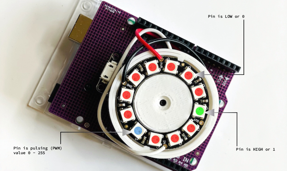
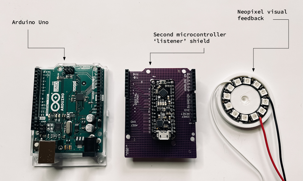
The aim of this Arduino Uno shield is to listen to input and output activity on the Uno pins and provide visual colour coded feedback based on the behaviour executed.
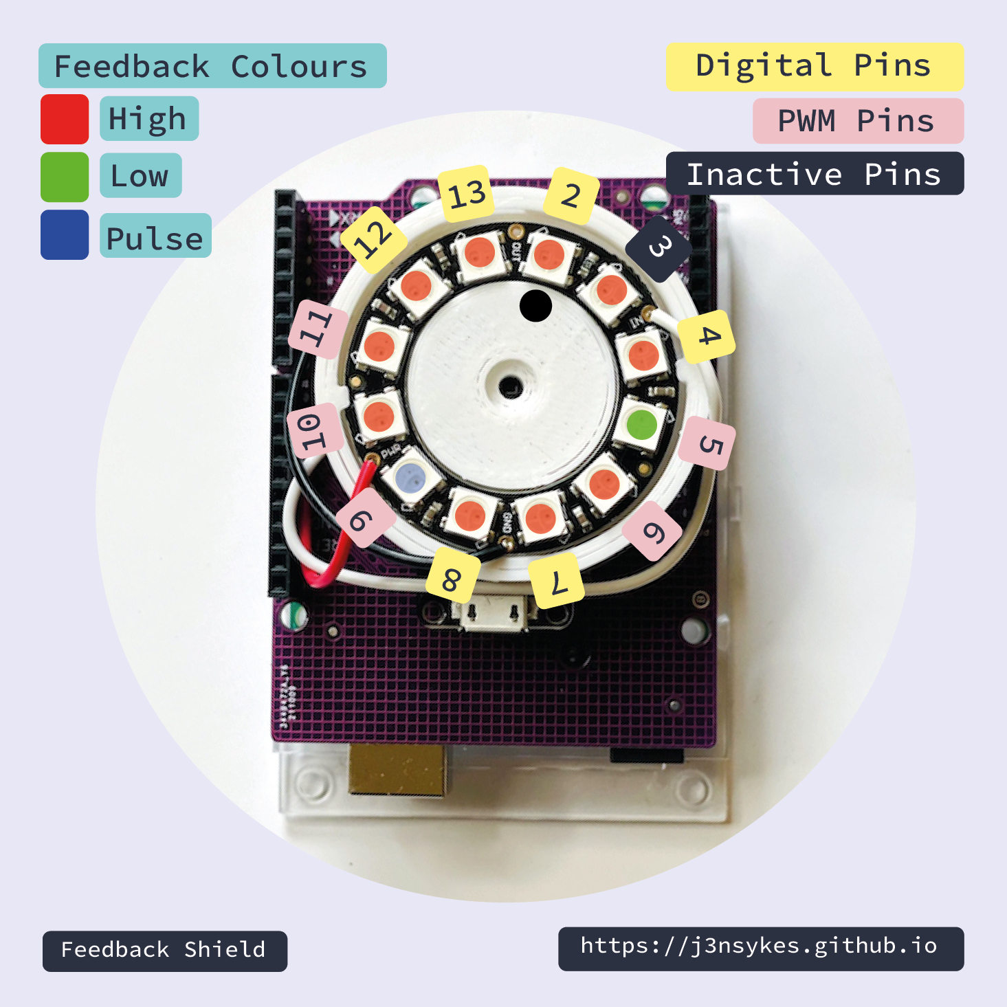
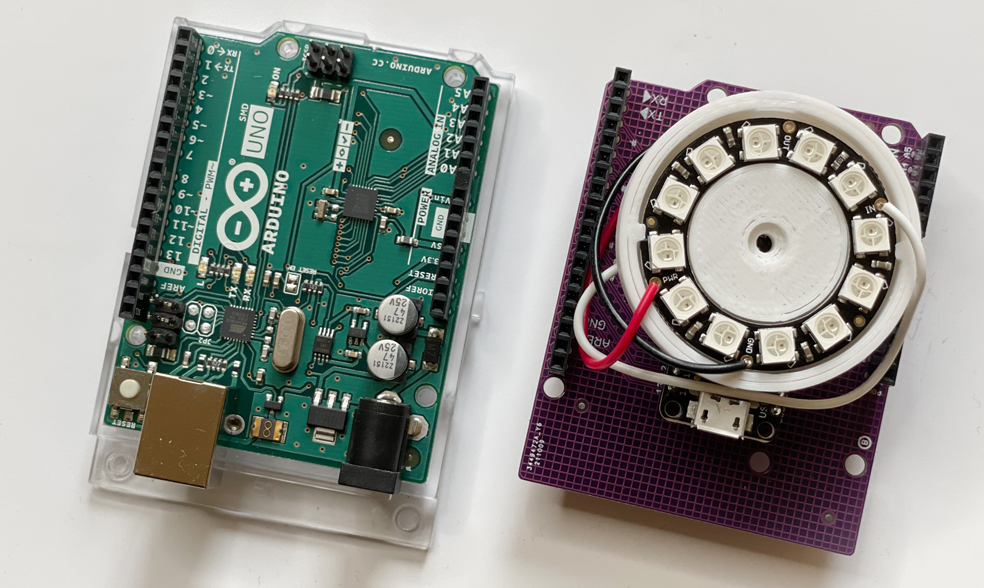
The shield consists of a second 'listener' microcontroller and a ring of LEDs.
Pin Guide :
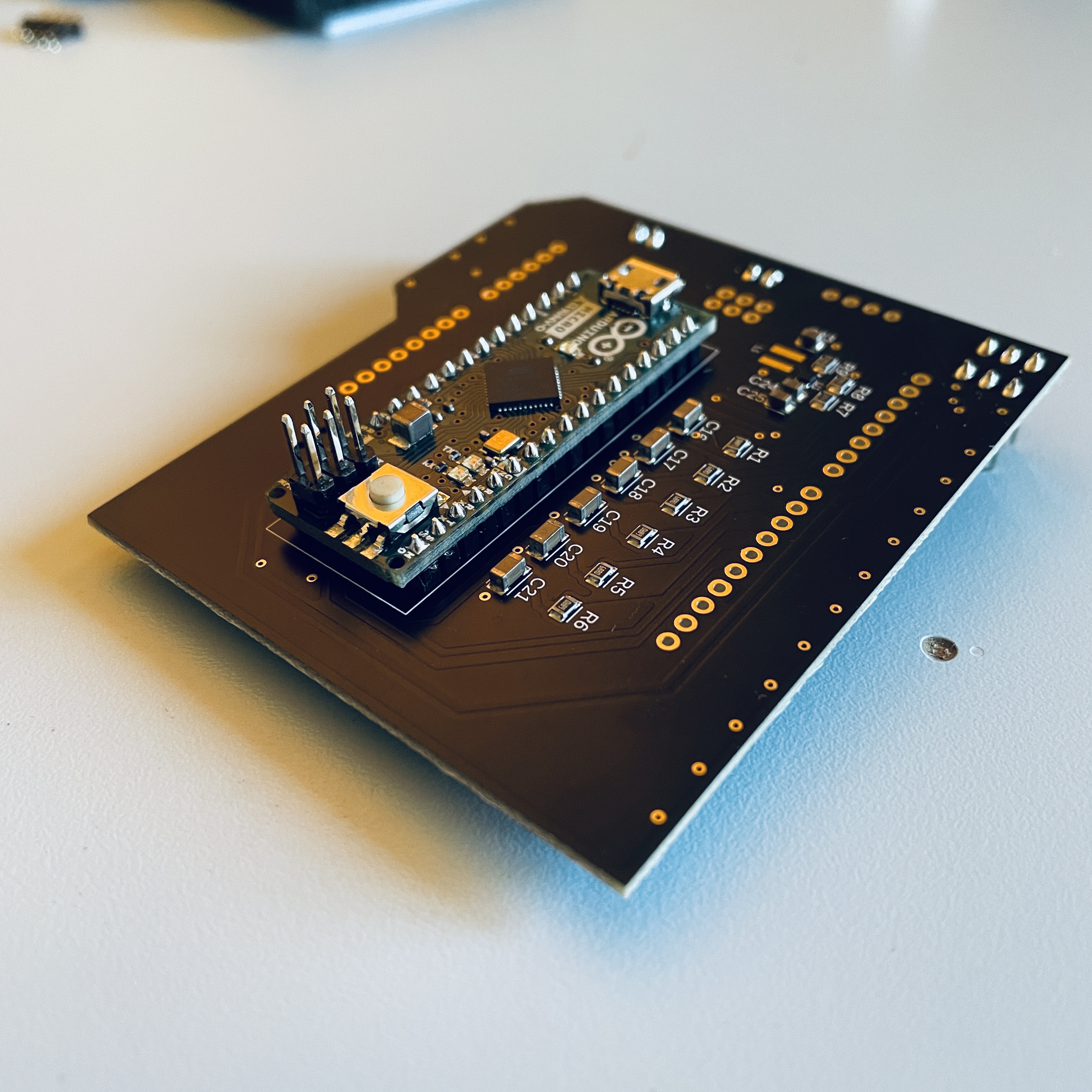
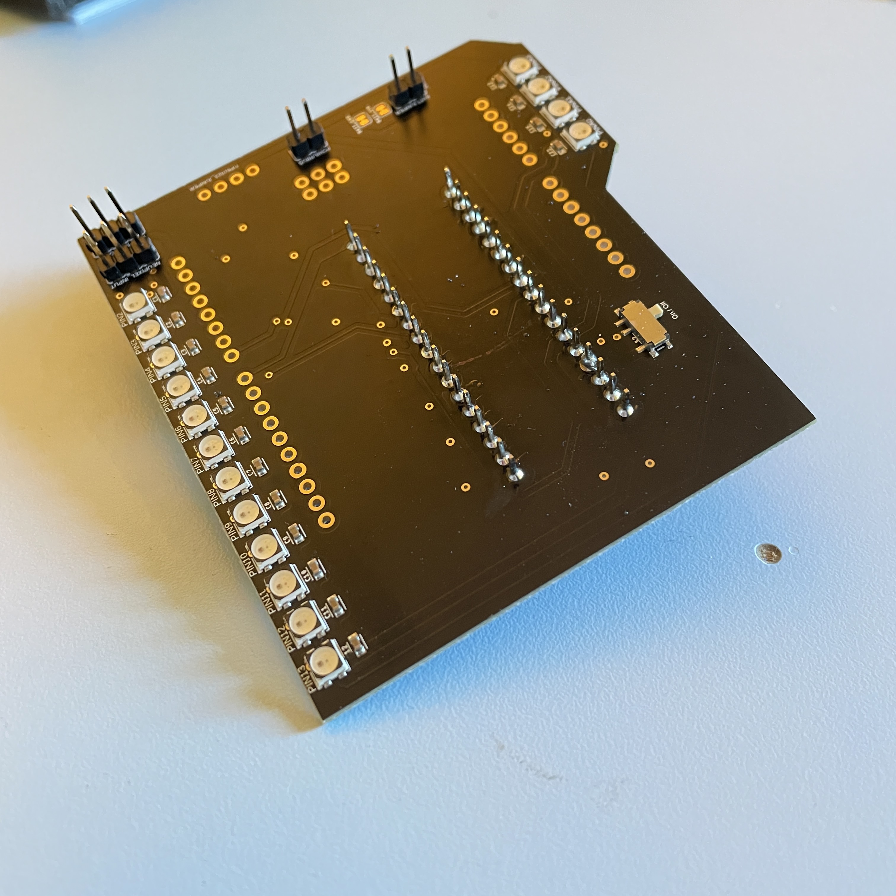
Some improvements and changes made to the design:
- The LED mapping will be paralelle to the pins
- Low pass filters integrated into the circuit for quick, low latency signal detection
- Surface mount soldered components for smaller, slim line profile